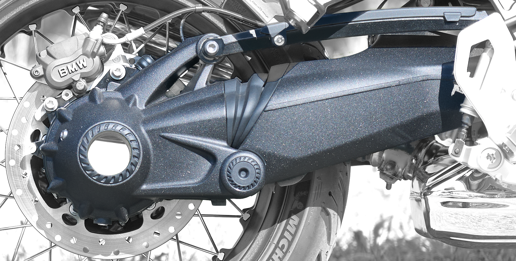
«Paralever» is what the BMW Motorräder company calls their rear wheel suspension/drive mechanism. The name is derived from the word «para»lellogramm, and the drive mechanism resembles in fact a parallelogramm-like structure involving several «levers»:
Motivation
The engineers at BMW motorcycles company devised and implemented this rather elaborate – compared to a simple legacy swingarm – construction in order to separate the horizontal forces during acceleration/deceleration from influencing the vertical rear wheel suspension movements.
The precursors of the R12 nineT with a legacy swingarm suffered from the unwanted coupling between the two – the notorious «rubber cow» (Gummikuh) effekt: during acceleration, with the accelerating torque acting in a CW sense on the rear wheel (as seen from the right hand side of a bike driving towards the right side), the corresponding reactive torque would act in a CCW sense onto the legacy swingarm, thus lifting the bike out of its rear wheel suspension.
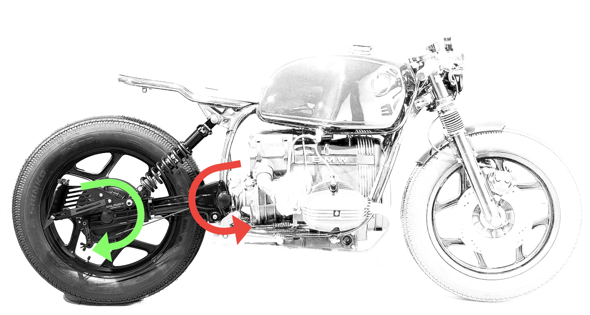
Likewise, during deceleration via engine brake, the reactive CW torque acts on the legacy swingarm and effects a squatting of the rear end.
Interactive Paralever simulator
In order to better demonstrate what’s special about the paralever construction I’m providing an interactive simulation where you can set a virtual model of the paralever mechanism in motion, providing two different levels of abstraction (LOD) plus some different geometry configurations.
Move the «Schwingwinkel [°]» slider and/or select a different «Config» to see the mechanism in action
Also, try the LOD «Schematic» to see how changing the position of a single pivot axis affects the degree of neutralisation of the «Gummikuh» effect in different variants of the paralever mechanism.
The paralever rear wheel motorcycle suspension is implemented as a four-bar linkage, with the swingarm and the torque support performing a rocking motion about their respective rocker links and the rear wheel drive unit acting as a coupling element between the two.
The paralever simulator features the swingarm (red), the rear wheel drive unit (blue), the torque support (greeen) and the two fixed pivot points of swingarm and torque support, marked by the white-blue BMW symbols.
The LOD setting of the paralever simulator allows for a «Schematic» or «Drawing» display of the various links:
- «Drawing» shows the rough outline of each link
- «Schematic» displays each link as a straight-line connection between its respective joints, preserving the distance between them and position of those joints. In «Schematic» display, I’m also showing straight line extensions of the swingarm and torque support as thin lines. The intersection of these thin lines (if there is any) marks the «instantant center of rotation (ICR)» (German: «Momentanpol«), the point where at this instant the movement of the coupling element is a pure rotation about.
In the Config section of the paralever simulator I’m giving the choice of three different locations for the fixed pivot point of the torque support, while keeping dimensions of the other links constant:
- Parallelogram: the fixed pivot point of the torque support is placed at the position, where both pairs of opposing sides of the four-bar linkage have equal length each, so a true parallelogram is formed. This is a fictuous point in that it is different from the actual paralever geometry. Note how the thin-line extensions of both swingarm and torque support extensions remain parallel and would intersect only «at infinity». This would equate to an infinity-length swingarm that fully eliminates any «Gummikuh» effect from the reactive torque.
- actual R12 nineT: this is as close as my manual measurement gets to the real R12 nineT paralever geometry. Note, how the thin-line extensions of the swingarm and torque support representations intersect at the ICR (see above). This is what BMW motorcycles is referring to with their claim, that the implemented paralever geometry acts like a legacy swingarm having 1.4 m(!) length. During acceleration, the same reactive torque applied to a much longer swingarm leads to a correspondingly reduced vertical force for the «Gummkuh» effect.
- legacy «Gummikuh»: in here, I set the distance between both fixed pivot points for swingarm and torque support to zero so they coincide at the swingarm axis. Note how the intersection of the thin-line extensions intersect at the swingarm axis = ICR, making all components share identical swingarm angles at all times – giving the mechanism 100% of the «Gummikuh» effect.
How does a Paralever remedy the situation?
If you start the above Paralever Simulator in a standalone window , switch to the «Schematic» LOD and cycle through the three Configs, you’ll see the following:
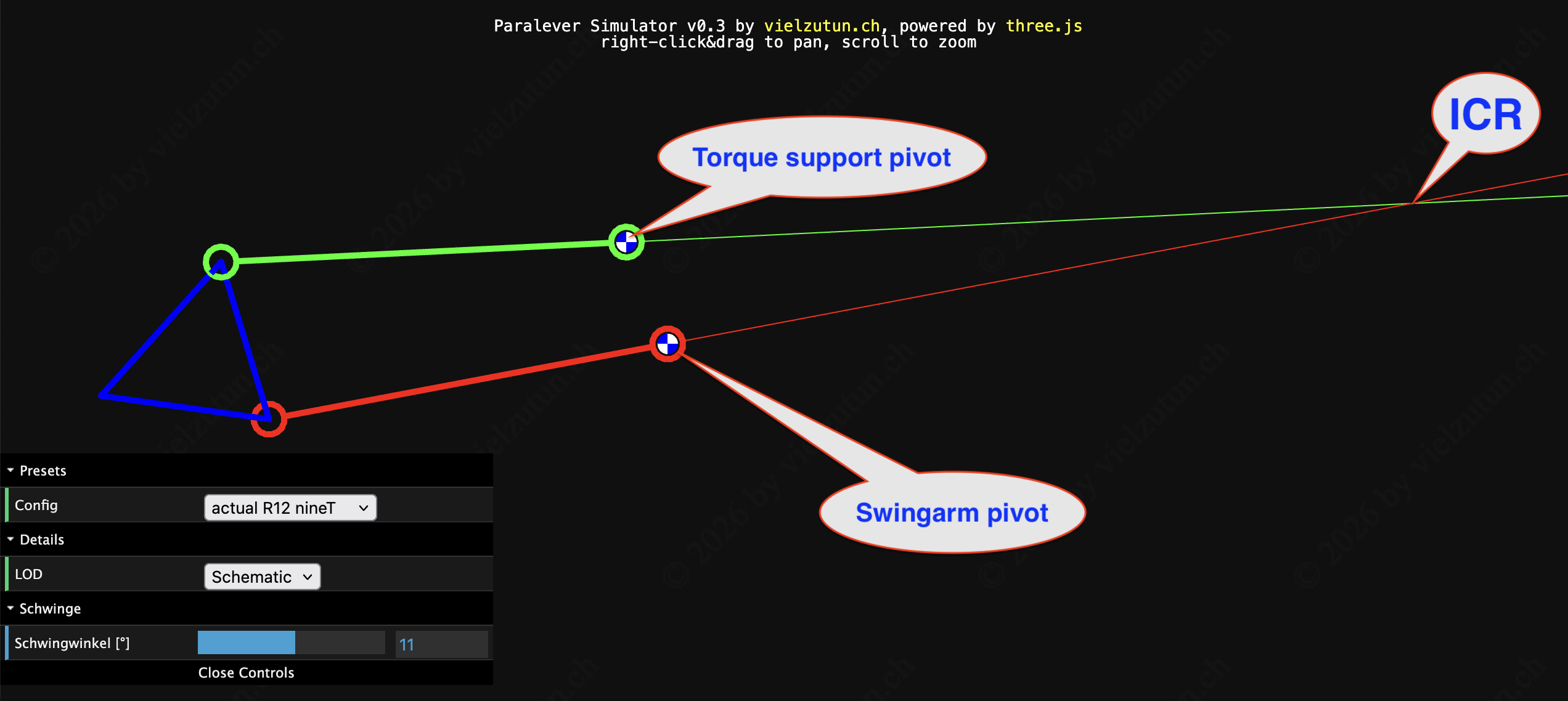
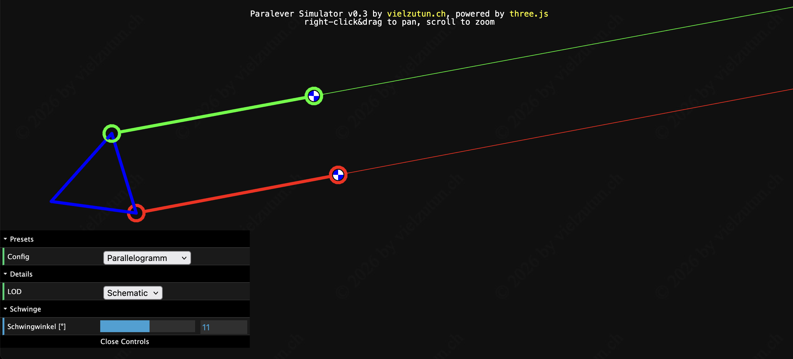
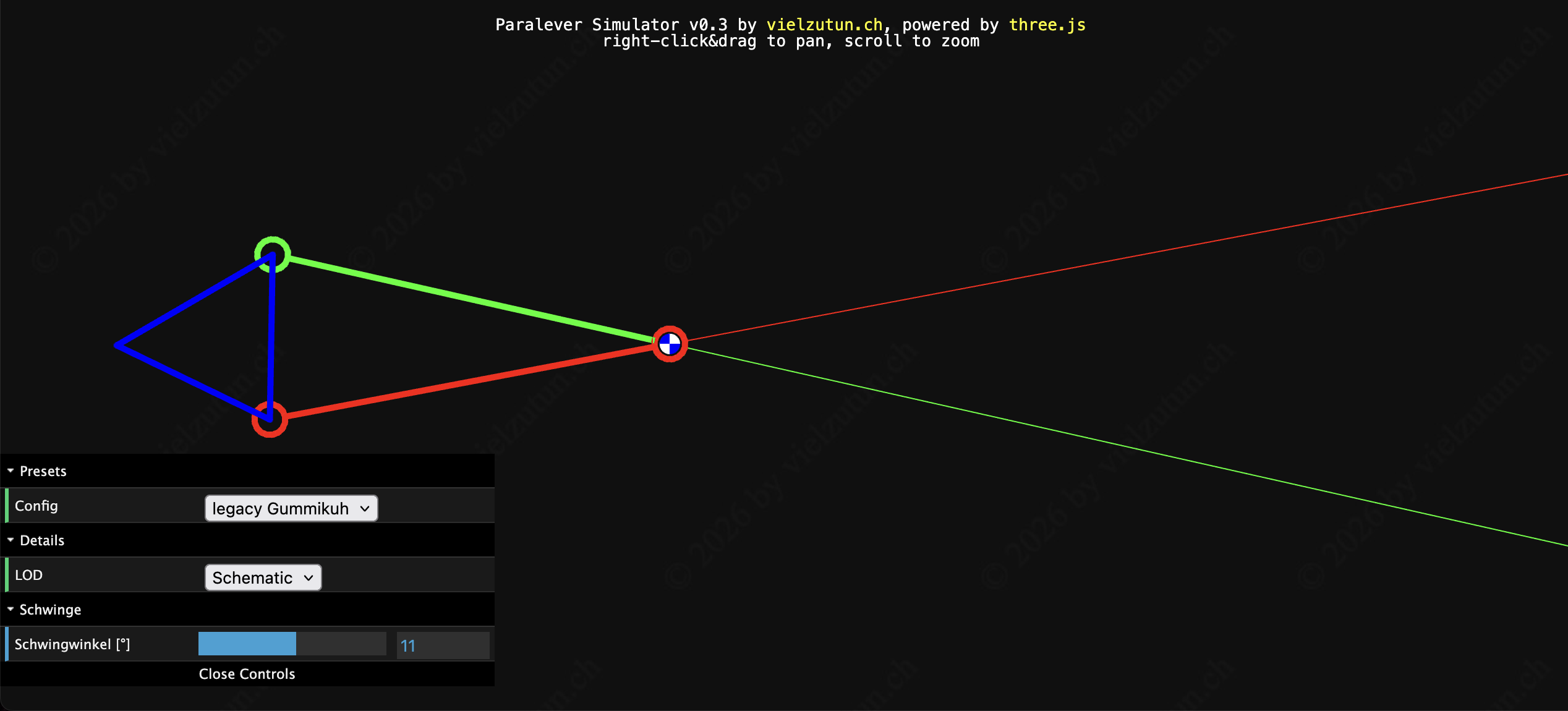
As you’ll have seen, the distance between swingarm pivot and torque support pivot dramatically influences the degree at which the «Gummikuh» effect manifests itself. Modifying this distance between zero and 160 mm gets you
| Distance [mm] | Effect |
|---|---|
| 0 | Full Gummikuh effect |
| 0 < dist < 160 | with increasing distance a progressively reduced Gummikuh effect |
| 160 | Full Gummikuh elimination |
This begs the question:
Why didn’t BMW go for a perfect parallelogram, which would have eliminated entirely the «Gummikuh»-effect caused by the reactive torque?
My personal take is: the engineers at BMW weren’t satisfied with eliminating the effect of the reactive torque alone. They wanted to eliminate all effects of horizontal forces on the vertical rear wheel suspension. Out of which the reactive torque is only the major one.
Dynamic wheel load shift
A second coupling between horizontal forces and vertical effect on the rear wheel suspension stems from the dynamic wheel load shift during horizontal acceleration: the initial wheel load distribution of approx. 50 : 50 between front and rear wheel shifts during forward acceleration and leads to an increase in rear wheel load and a reduction in front wheel load. In extreme cases this can result in a «wheelie», with the full weight of bike plus rider borne by the rear wheel alone. Obviously, this leads to an additional compression of the rear wheel suspension.
So you have a squatting effect due to the dynamic wheel load shift during horizontal acceleration and a residual (rear-end lifting) «Gummikuh» effect from the only partial compensation of the reactive torque acting on the swingarm.
It would make perfect sense to adjust the reduction of the «Gummikuh» effect such that it neatly cancels out the inevitable squatting effect from the dynamic wheel load shift, and I guess, that’s exactly what BMW’s engineers did.
The anti-squat effect of dynamic wheel load shift on the rear end during deceleration via front and/or rear brake is not influenced by the paralever. But that’s a different story …
Trivia
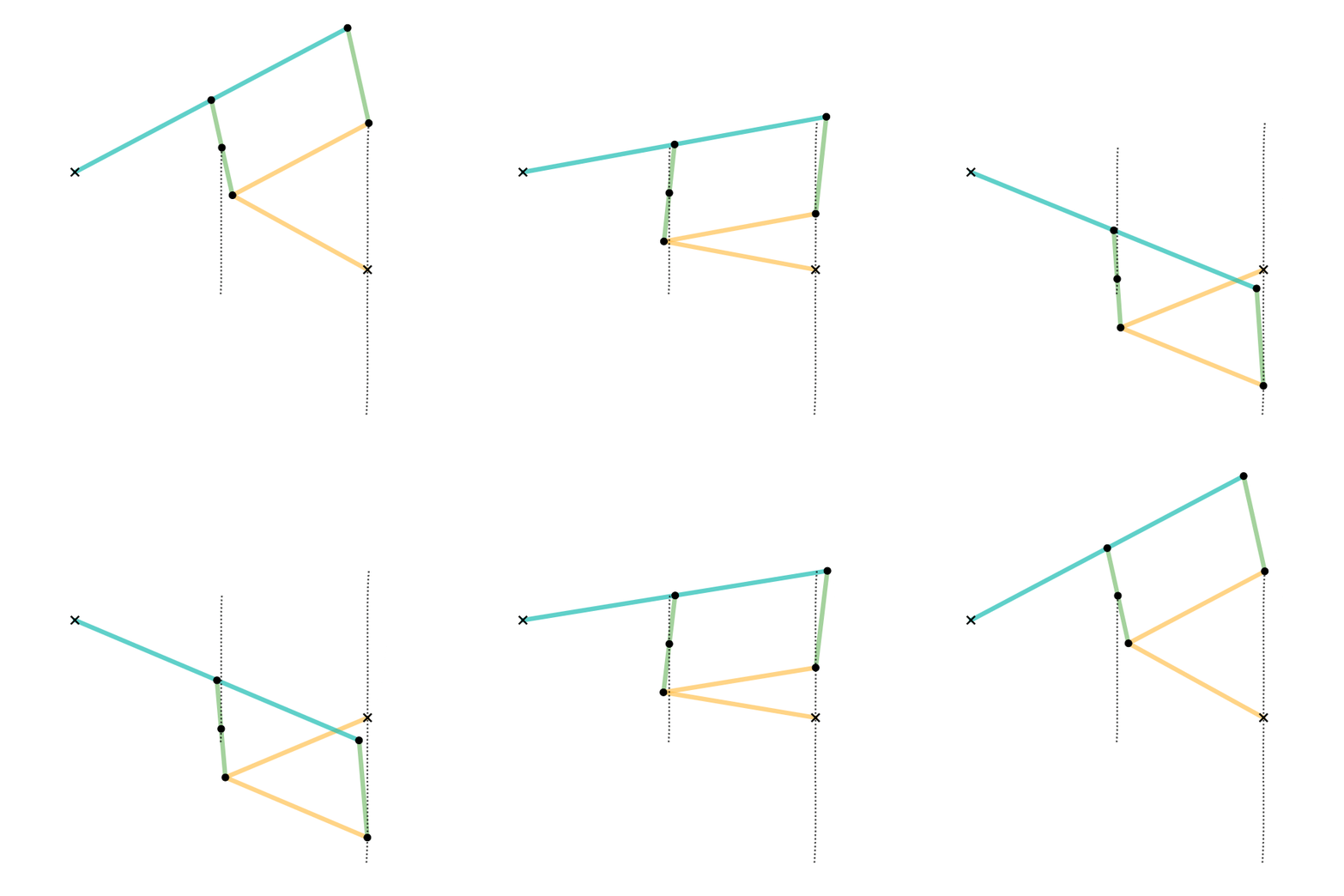
- The advantageous properties of parallelogram(-like) linkages have been known by engineers for almost 250 years. See, for instance Watt’s linkage, invented by James Watt in 1784:
- The invention of the pantograph having a parallelogram at its core even dates back to Heron of Alexandria (probably 1st or 2nd century AD).
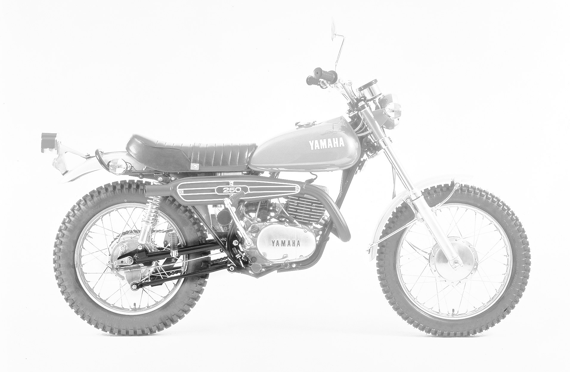
- Fun fact: my very first motorcycle, an early 1970’s Yamaha DT2 already had a parallelogram rear brake force deflection right into the frame itself, to avoid rear wheel hopping during deceleration via rear wheel brake: