
I’m in the process of adding a dedicated oil temperature gauge to my R12 nineT. The following is a rough visualization of what I want the result to look like:
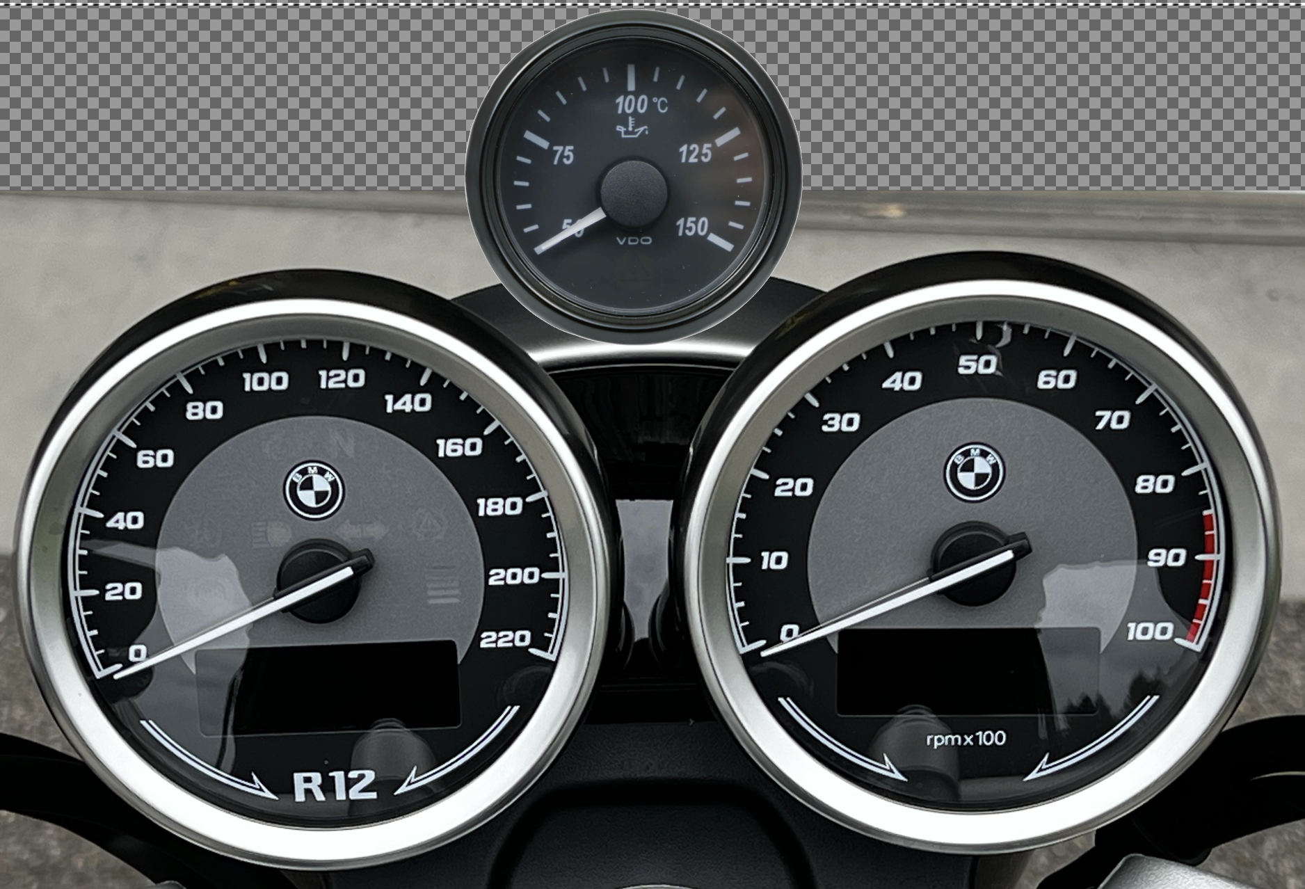
I’m aiming for a technically sound and visually unobtrusive solution, which is why I excluded any digital and/or non-circular alternatives. The selected VDO SingleViu gauge fits my bill for its simple dark and light grey design and its future-proof features in that it allows both a legacy analog connection as well as a digital integration into a CAN-bus environment like the R12 nineT has. To round things off, a chromium bezel ring could be retrofitted once I have it up and running.
Motivation
Why would one want to add an oil temperature gauge in the first place?
The 2026 R12 nineT comes stock with a mere tri-state «engine temperature» information: «COLD-OK-NOK/HOT». If you exclude the two minute interval at the start of a ride when the engine is COLD, you are left with the binary information OK-NOK for the remainder of the ride. You never know, how far you are away from an overheated engine – everything seems OK, until all of a sudden it might not be anymore.
The R12 nineT has an oil/air cooled engine. Oil is an integral part of its heat management. Even though the bike comes with a small oil cooler, no fan is provided. As I’ve detailed in my discussion of the heat management of my former Monster 1200S, a cooler doesn’t do anything if there is no air flow, like during a traffic jam.
I just want to know the thermal state of my bike while there’s still time to react and I’m able to adjust my treatment of the bike.
Three challenges
Im faced with three areas of challenges:
- the gauge
- the sensor
- the electrical integration
The gauge
I selected the gauge already, as outlined in the intro. The challenge will be, to attach the gauge «somehow» in a position as shown in the introductory image. To that end, I’ve designed a three-ringed bracket which is currently being lasercut from a 2.0 mm stainless sheet metal by a hired contractor:

My plan is, to clamp my above beautiful bracket between parts #2 and #3 of the instrument assembly, then fasten the additional gauge through the third, smaller ring via the provided locknut.
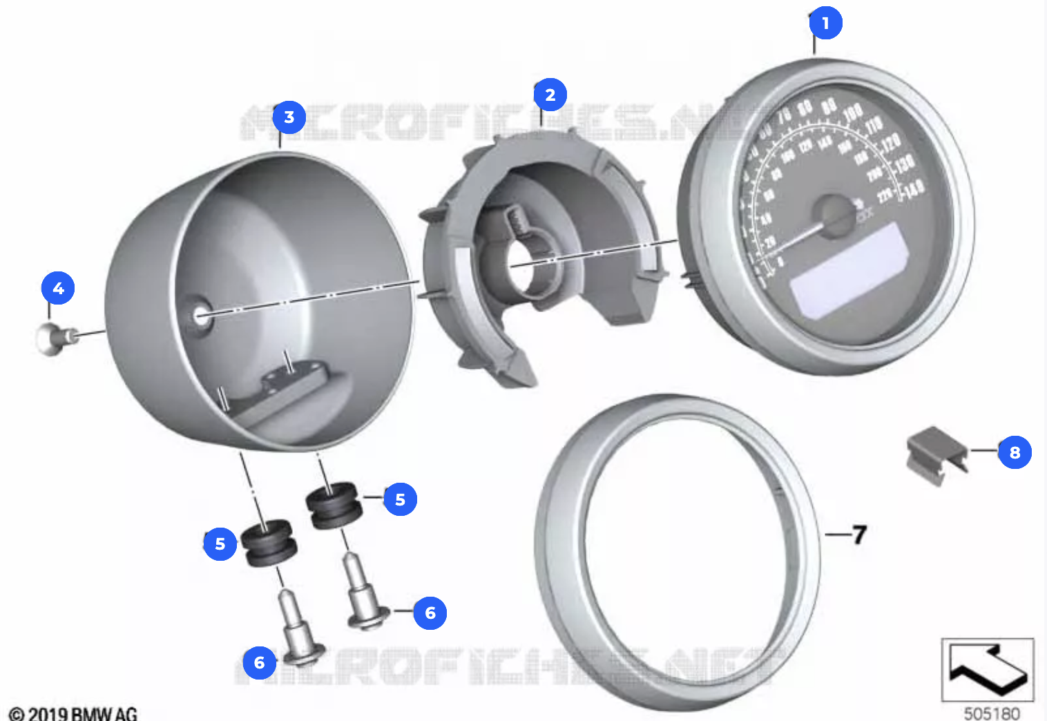
Let’s see how far that gets me. 🙄
The sensor
As a minimum requirement, the sensor must be compatible in its response curve to what the gauge expects. To be on the safe side, I picked a sensor from VDO, the same supplier as of the gauge I selected, which supports the intended temperature range.
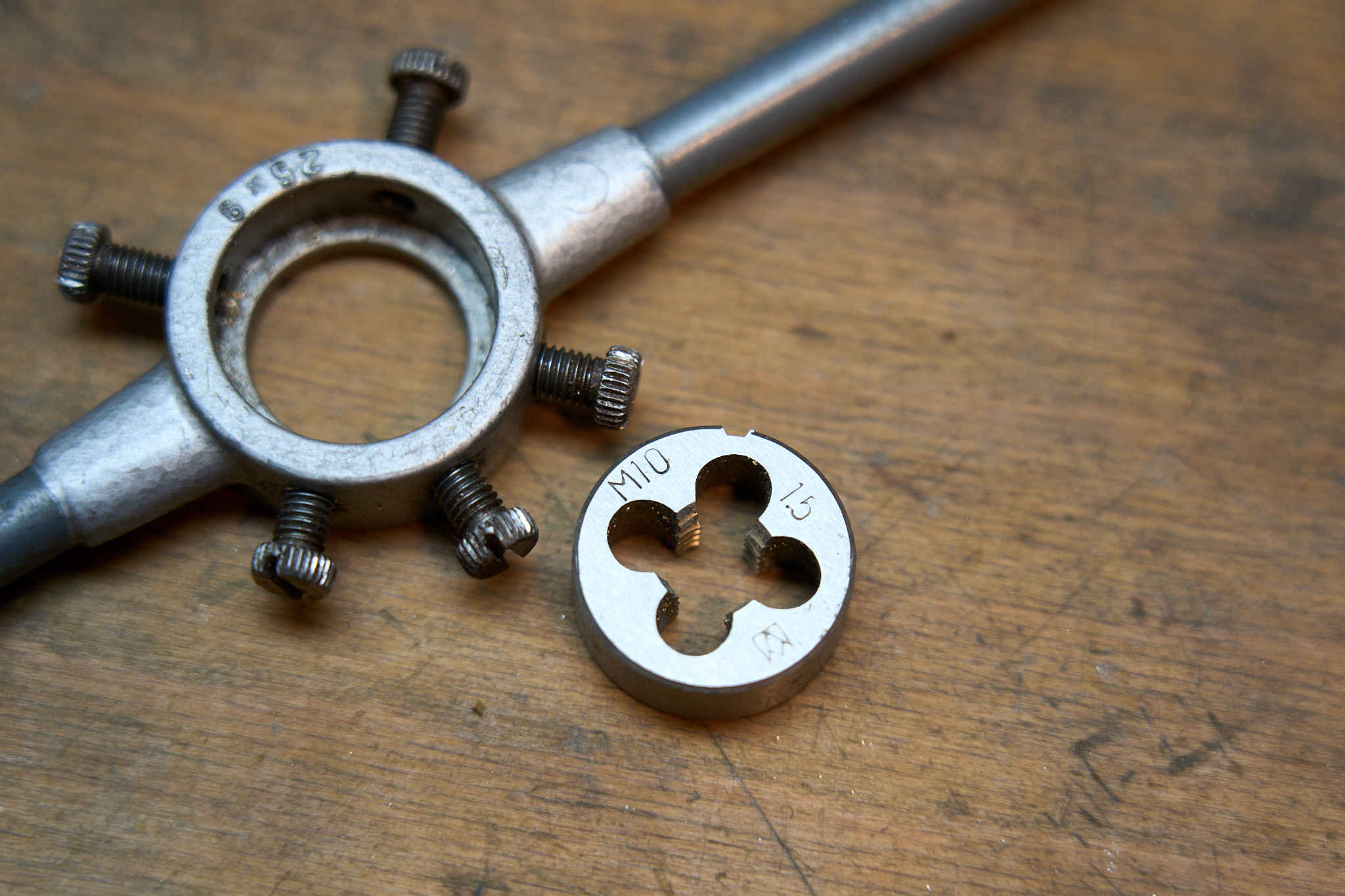
Then there is the question of sensor placement. The sensor placement is closely linked to the sensor’s fastening thread. I was luckily able to realize my #1 preference, which is a blind, threaded bore on both right and left side of the oil sump casing. The bores are M10x1.5 each and reach ≈30 mm into the sump.
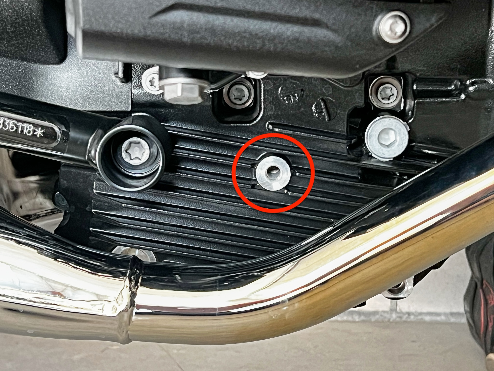
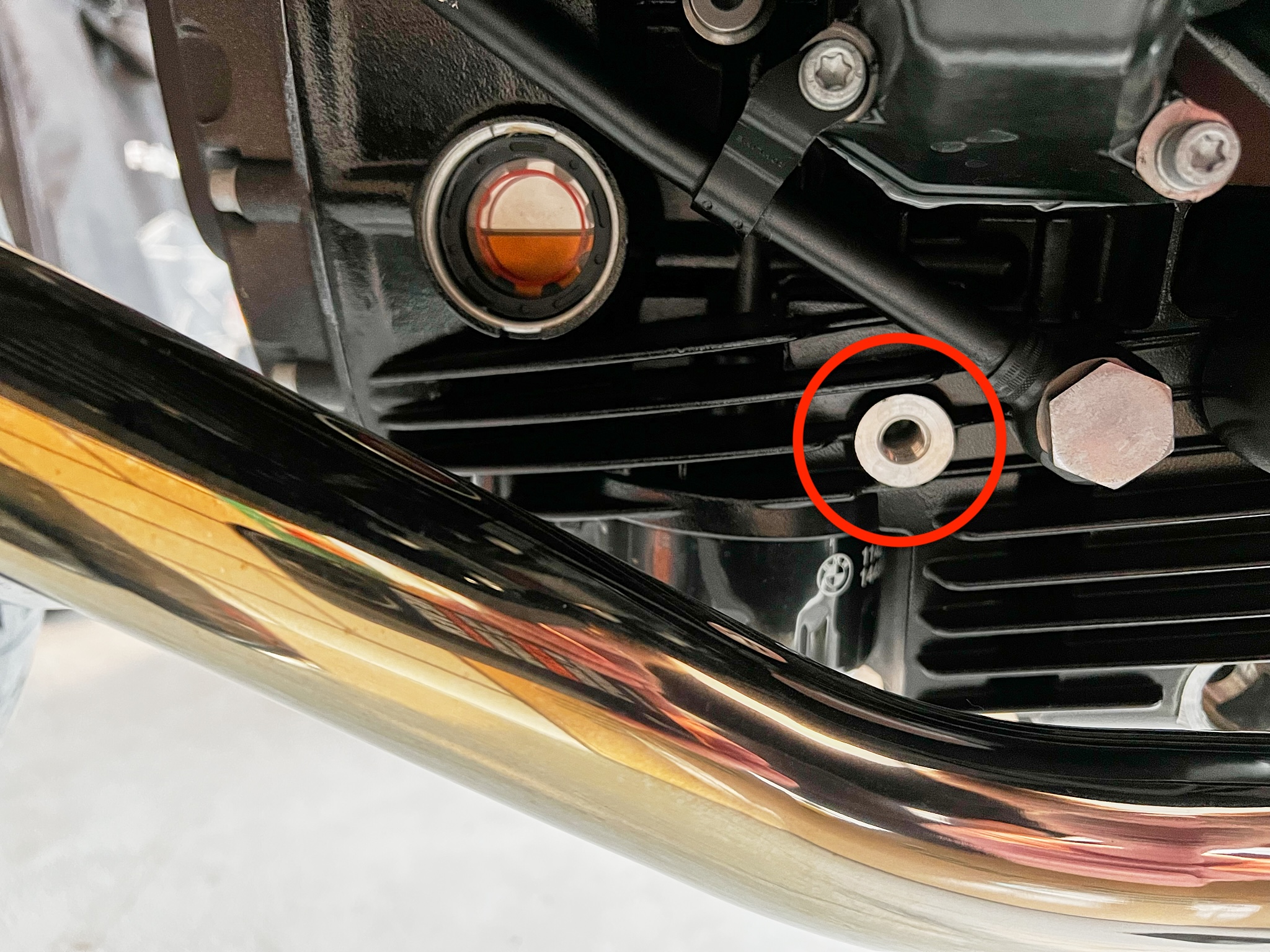
These are my preferred places, as they are sufficiently deep below the oil level in its sump (even accounting for some oil in circulation), and don’t require tampering with on each oil change. So I’m expecting this to basically be an «installation and forget» kind of thing.
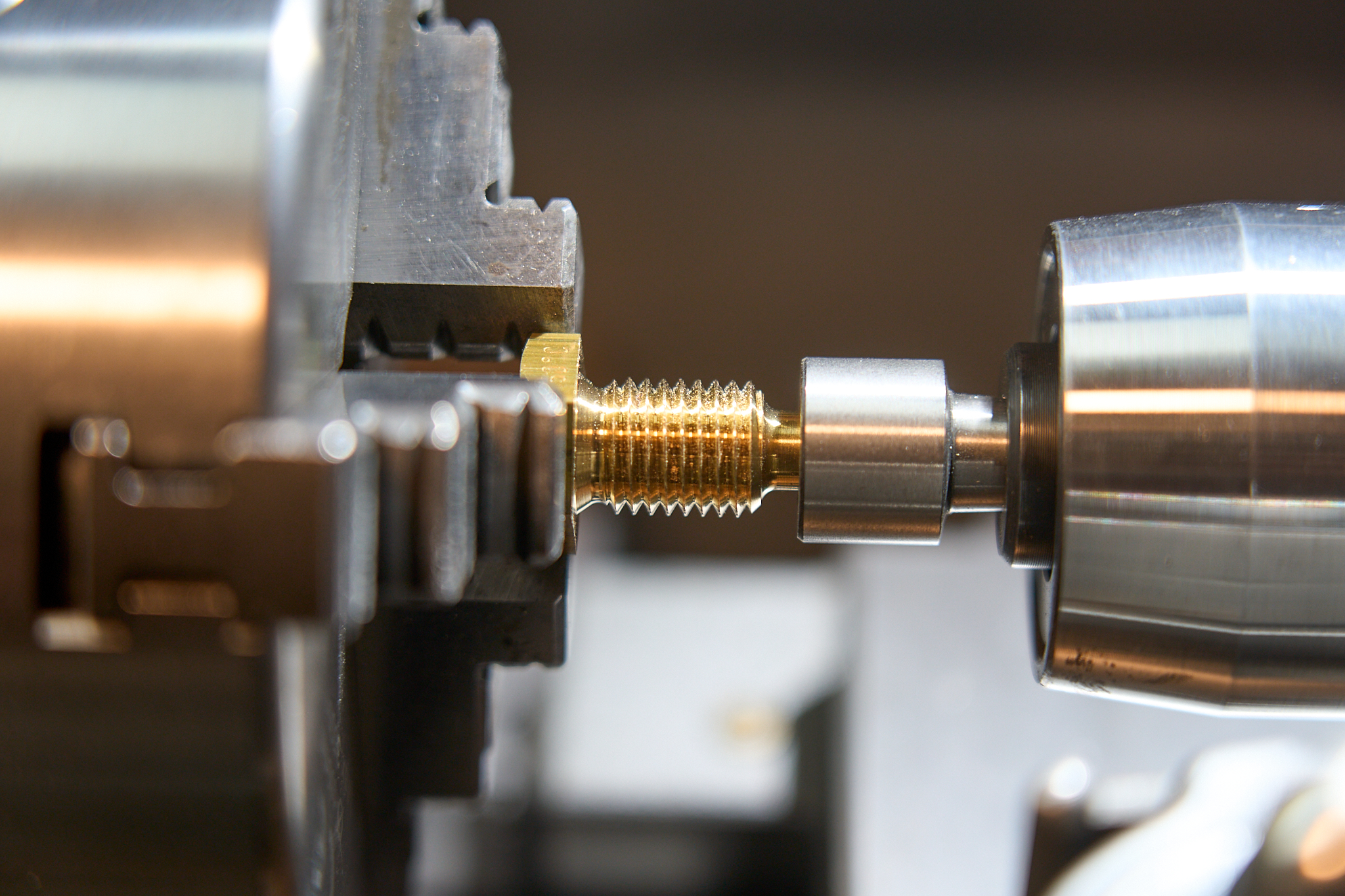
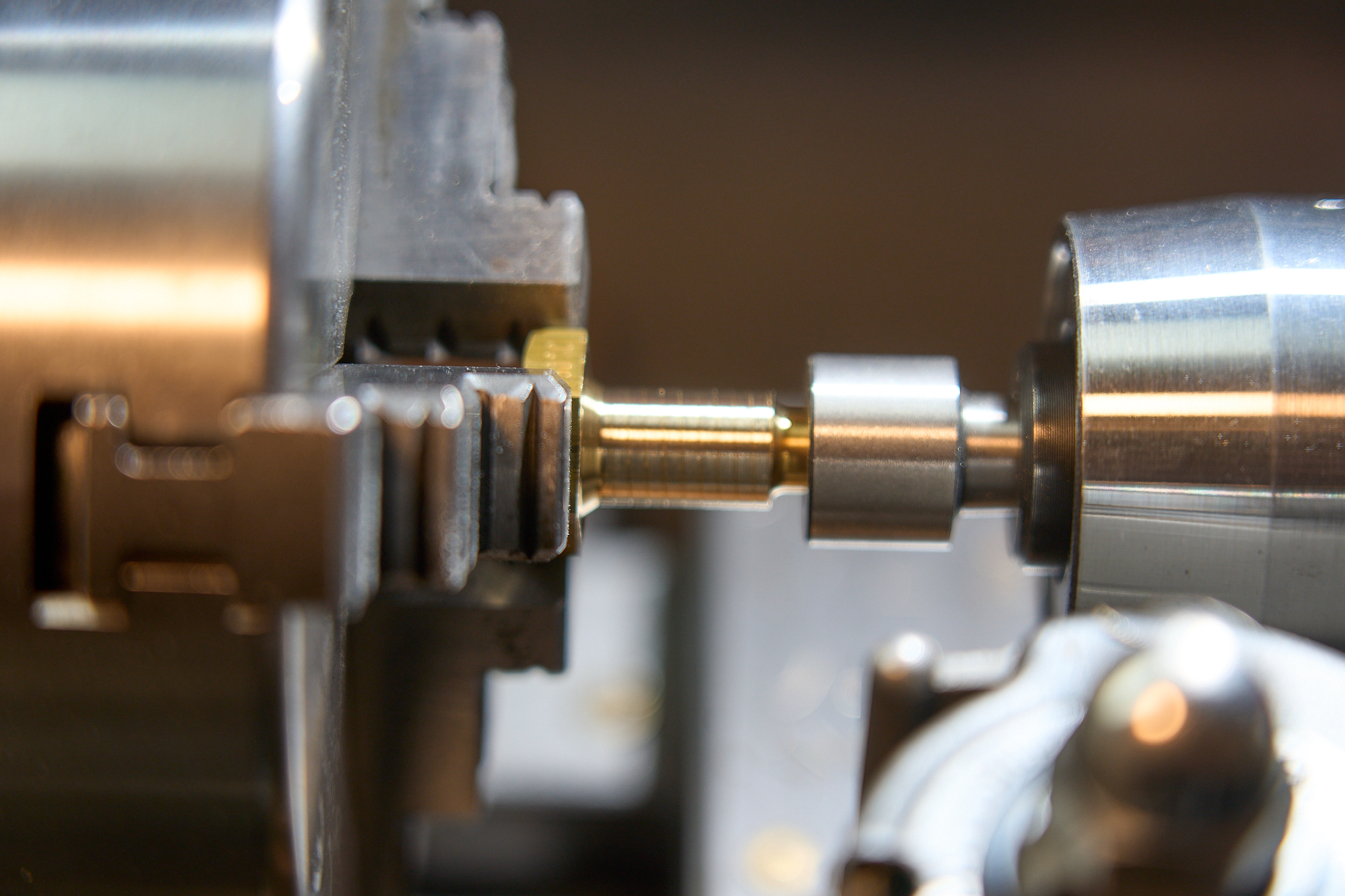
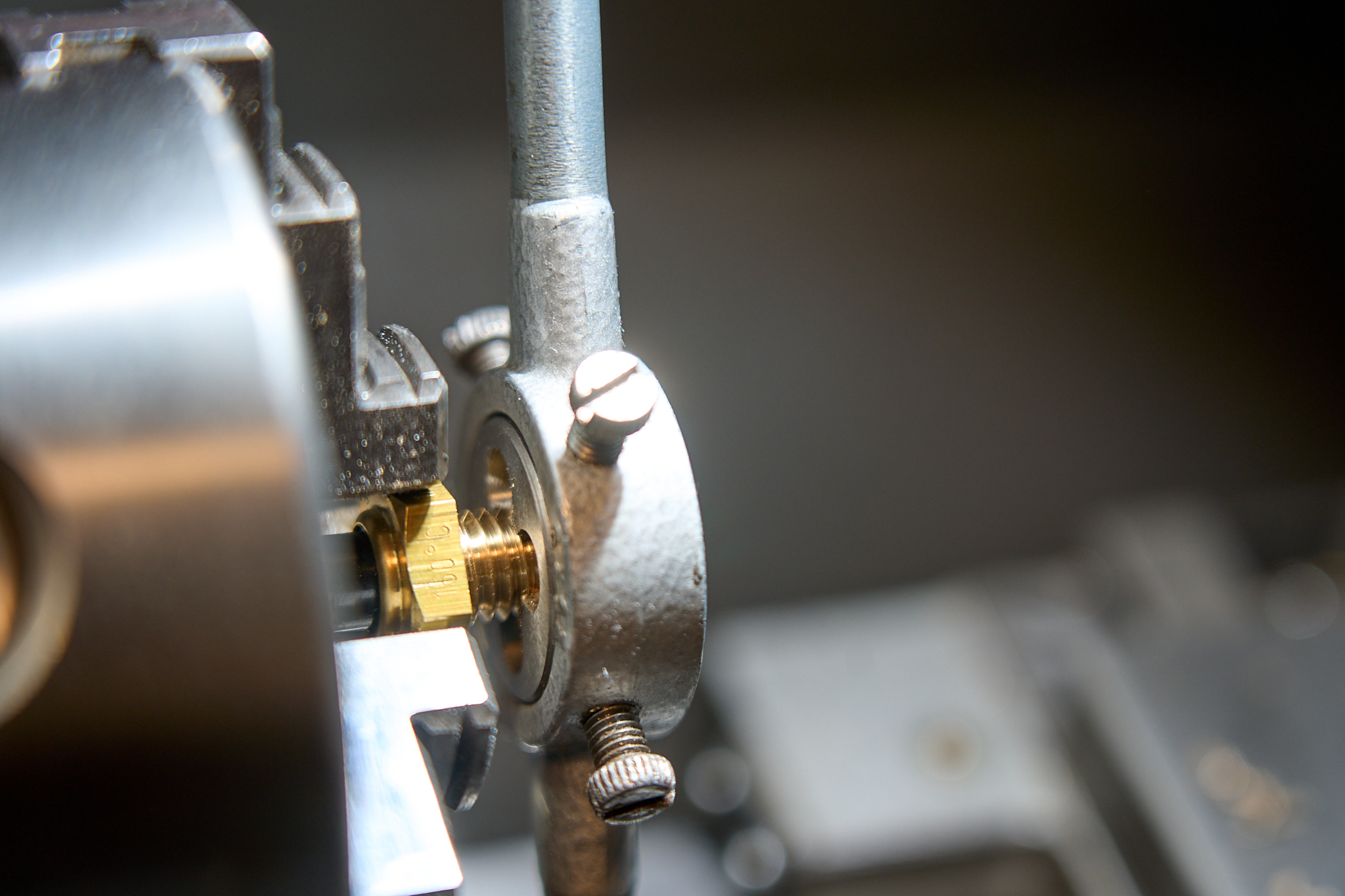
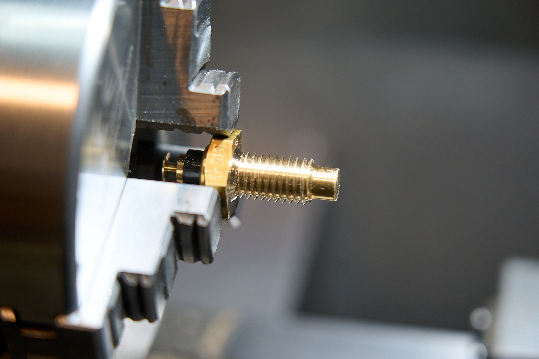
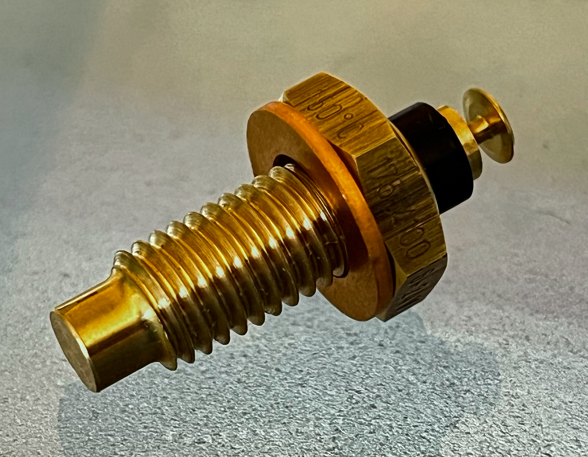
Why was I lucky to be able to use one of these locations? Because even though a VDO sensor having a matching M10x1.5 thread is listed on many vendors‘ websites, they are always listed as «discontinued». But then I was able to re-thread an available M12x1.5 (new part number: 17554100) sensor down to the required M10x1.5 on my small lathe 💪
The electrical integration
The electrical integration can thankfully be done along the legacy analog path, as well as the digital CAN-bus integration path. For my current lack of expertise in CAN-bus related stuff, I’m opting for the legacy analog path.
The bits of information I’ve so far collected comprise a two-wire connection of the sensor to the gauge, with a dedicated sensor ground wire. Also, there seems to be a requirement as to the positive (+) power supply, which should be switched through an ignition powered relais, as well as a «permanent» positive (+) power supply which is supposedly required for an «orderly» shut-down of the gauge, as well as the proper storage of «some values». Thankfully, the quiescent current is allegedly < 3 mA, so it hopefully wouldn’t noticeably drain the battery.
These are only hear-say rumors so far. I’ll update those, as I gather my own experience along the way.
Stay tuned and come back for updates!